
Introduction

The following page describes some of the amplifiers built in the last few years, together with a few observations about things that have been discovered en-route.
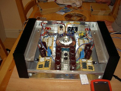
EL34 SE

This EL34 is a really ballsy little performer and with its astounding 5 or 6 watts per channel it really punches way beyond its weight. The circuit is a standard single ended design, variations of which seem to have been in common use in the 1950s. Examples of this circuit can be found all over the internet by using a simple search. My particular circuit uses a 6SN7 as a driver, in contrast to most of the examples that I discovered, which use a 6SL7. I found the 6SL7 a touch brittle in the sound, and far too easy to overdrive if the source happened to be a bit fiery. I personally favour the 6SN7 and have found it much easier to get a satisfactory operating point. In addition, although not strictly necessary, my version uses a power supply with parallel GZ32s ( some wag commented that this must be the twin carb version).
Wiring
After deciding the layout of components, the tag strips, heater wiring and earth buss are fixed in place. The Ac heater wires are twisted and placed well into the corners. I have used small strips of aluminium to hold the tag strips onto the bolts that fix the transformers. This arrangement seems to work well and leaves plenty of room for component placing.

All components added. This may have ended up a little neater using tag boards but it does work and it is easily adjusted. The next build will definitely be a bit neater with tag boards or a better layout of components between tag strips. This layout resulted in no hum whatsoever when used with the Ariel speakers. There was slight hum detected when hooked up to the vofos but it was only audible with an ear right up against the speaker. It bothered me, so I measured it, it was 2.4 mv, which I understand is not bad at all for an amp such as this.

Completion.

And here it is hard at work in the project studio rack. It is used primarily for mix monitoring as I find it both ruthlessly revealing and also fantastic at portraying a razor sharp soundstage. I deliberately used the more expensive Hammond transformers as I was curious to hear the best sound such a simple circuit could produce. I was not disappointed. I am sure that a damn good sound could still be produced for half the price however, simply by using the cheaper Hammond transformers.

This amplifier cost the princely sum of £370 to build, but as mentionedel above, it could be built for a lot less. I'm pretty sure, having listened to lots of shop bought amplifiers, that this kind of sound cannot be bought off the shelf for anything near this price. So, if you happen to be reading this because you fancy building a single ended amp, then its not a bad place to start.
Value for money....6 stars!.
Firstwatt F2
I had wanted to build one of Nelson Pass's amplifiers for some time. Although never having owned one before this build, I was seduced because he had become a bit of a folk hero due to his generous philosophy of providing the DIY community with his designs. Originally I wanted to build one of the large Aleph amps to drive the electrostatics, as this combination of amp and speakers has been spoken of with reverence in many corners of the interweb. The main reason for not actually doing it has been the difficulty in obtaining heatsinks here in the UK.
When Nelson announced the First Watt series of current amplifiers for single, full range drivers, it coincided with my exploration of the vofo cabinets. This was obviously a sign from above so I decided to try harder and really build one.
I really did have to try harder, the heat sinks ended up being supplied by Conrad in Australia. I tried a number of suppliers in the UK but they couldn't come near the price of the Australian product, and that was even counting the cost of shipping. I think its fair to say that without Conrads I wouldn't have continued this adventure.
So, to the amp, its described as a transconductance or current amp, single ended class A with 5 watts or so of power, Being a current amp it isn't ideal working with normal, multi-way speakers due to interaction with crossover networks and is therefore aimed at the high efficiency single driver type of speaker.
All the background information for the First Watt amps can be found here.
The schematic for the F2 can be found here
Construction
The circuits were built on standard matrix board, using the wire from standard twin and earth mains cable to provide the tracks. This method had proved workable from the Ariel loudspeaker crossovers so It was used here.


The layouts for the matrix board :


A reverse of the layout was used for making a mirror image for the second board. Take care to reverse the transistor connections if using this mirror method.
The build method has been dictated to some extent by the nature of the Conrad sinks which have flanges on the sides. I have built my boards to align the transistors with the flanges but they could equally have been built to suit flat heat sinks. The important figure in all this is the heat coefficient of the sinks. I may have over specified with these particular sinks as my amp only gets warm. I know from many sources that some of the Pass Labs amplifiers get very hot and still perform well within specification.
The chassis for this amplifier is one piece of 2mm aluminium which has been bent to suit the dimensions of the heat sinks. This forms the bottom and the back of the chassis, to which all parts are connected. A duplicate piece could be used to form the top and the front. My pieces were supplied by Pat Shears of MTGG in Hull who is a real wizard with aluminium (contact details can be supplied on request).
The sound
This amplifier has been a bit of a shock to me. To say that I am a valve fan would be a bit of an understatement, so to an extent, this amp goes against the grain. But I want to remain open-minded, so here we are....and wow....
It has a very beguiling sound. It is fast, very detailed, and it has that crystal truthfulness about it. This amplifier really lets you climb inside the music and focus on any part you wish, or, conversely, it allows you to pull away and just get lost in the big picture. I can't detect any bias for any particular part of the music, or any particular type of music, so in that respect I would have to say it is very neutral.
In making comparisons with my other set ups I would have to say that this one is different, very different. In direct comparison with my KT88 I would say it has a different, perhaps lighter, bass response. Without a direct comparison though, this fact may not be readily visible. This amp certainly presents the music in a different manner. To use words and phrases that I hope are universal I would say that this amplifier is bright, bouncy and very precise, although by no means fatiguing. It is one of those additions that has forced me to re-visit my entire music collection because form the first playing it dug out something that I hadn't heard before..
I have to say that I am really glad that I built this one. It was an absolute dream to build and the resulting sound is truly rewarding. Even if it had been a real pain to build it would still have been worth it. In comparison to my other amps the value for money on this one is off the scale.

Firstwatt F4

Construction
The experience of building the F2 was a great asset and certainly helped by making this project a very easy build indeed. For the construction I used the tried and tested Conrad heatsinks, although this time I used the ones without the flanges. I also used the one-piece wrap around base and back. This time, however, I used the ready made circuit boards produced by Peter Daniels and distributed as a group buy on the DiyAudio forum. The boards were around £15 for a pair and represent fantastic value.
To spread the heat exchange I elected to space the mosfets along the heatsink and connect them to the circuit board by wires. It was suggested that this method may lend itself to interference and oscillation due to the distance between the mosfet gates and their resistors, but this has not proved to be the case.
The layout for my elected build can be seen in the photo above, and the background and circuits can be found on the Firstwatt website here.
If you want to try this by hardwiring on matrix board then a suggested layout can be seen here. This layout is untested so use is at your own risk and pay attention to device orientation.
The layout shown above indicates the transformer at the back and the power supply at the front. One improvement that I would recommend if following this route would be to reverse this arrangement and locate the transformer at the front of the amplifier. This would minimise the risk of RF interference to the sensitive input wires from the transformer.
Even without the experience of building an F2 previously, this build would be extremely simple, and well within the capabilities of a first-time amp builder.
The Sound
This is not officially an amplifier, a more exact description would be a buffer as it has a gain of 0.9 in the standard configuration. Having said this, the following summary relates to the way I have driven my F4, i.e directly with a squeezebox or via digital interface and outboard DAC. Differing preamps will doubtless produce different results but a general rule of thumb would be that the preamp will require some oomph to get the best from the F4.
So, the sound, Fantastic!
This is the best solid state amplifier I have ever heard. I thought this when I first built it and I still believe this after listening consistently since 2007. It is not better than any of my valve amps but it is different, and it is enjoyable, and it is very much cheaper to build. I have not detected any faults or failings in the amp in all the time I have been listening.
In truth, I find the F4 a touch more clinical and dry than either of my current valve amplifiers but this can't be considered a criticism as it makes a refreshing change to switch between amps. In general terms the F4 has a very valve like presentation to my ears.
Conclusion
I have presented this amplifier at a number of valve enthusiast meetings and all that have heard it have complimented it. This, to me, is praise indeed. It really does have a very valve like sound, and was particularly well received when driven by an Aikido preamp. I have successfully driven my full range electrostatic speakers with it, when driven by a squeezebox front end, so I can say with some conviction that it really is very versatile.
If you are one of those valve fans that likes to criticise anything solid state, then all I can say is give it up for a week and spend the time building one of these. I can guarantee you will be pleasantly surprised and the whole thing wont cost any more than the price of one output transformer. It was a lesson to me.
Firstwatt F6
This one has been a long time on the work bench. This project started in 2012 but got side tracked and was only completed in April 2015. During this time the project changed somewhat, and instead of the Semisouth Jfet version which was first announced by Nelson on the Diyaudio forum, it ended up as the Diyaudio version which uses IRFP240 Mosfets in place of the Semisouths. The Semisouths are still in the bit box waiting for a suitable project.
There is a long thread relating to this circuit on the Diyaudio forum
Construction
It was decided to build this circuit from scratch but for the less confident it is understood that a pcb for this amp will shortly be available from the diyaudio site. The matrix board that was originally used for the F2 project seems to have become hard to find so it was decided to build this circuit on standard paxolin board. This caused a slight variation in the build process as the paxolin obviously needs holes drilling for the components.
The method used was to draw the circuit out on a sheet of paper with as few overlaps in the tracks as possible. It turns out that it's possible to draw this circuit with no overlaps at all. This drawing was then transferred to a piece of paper the same size as the paxolin board, drawing all the components actual size. The drill holes can then be marked on this piece of paper. If the tracks are actually drawn on this paper then they can be used to bend the copper wire correctly for soldering underneath the board. This paper can then be fixed to the paxolin board with sticky tape and used to drill the holes in the correct locations. The following images show the actual drawings used for the circuit boards.
The circuit boards :


The circuit boards have been attached to the heatsinks with 15mm stand-offs, fastened to the heatsink and the board with m3 machine screws. The heat sinks are the same as used in the other firstwatt projects, i.e 300mmx150mm from Conrad in Australia, specified at 0.25 degrees per watt.
The boards were laid out to allow the mosfets to be fixed near the bottom of the heat sinks(heat rises!), and spaced out across the heat sink to spread/share the heat transfer. As was mentioned earlier the jensen transformers were located toward the back of the case, as far from the mains transformer as possible. The 15mm stand-offs were chosen as they proved to be the matching size for the legs of the mosfets when they were attached to the heat sink.
The mains transformer was 2x18v 300va obtained from airlink, with all shielding specified on the order. Experience with the F2 build had shown that these toroids do emit an amount of hash so it was deemed prudent to ask for as much shielding as possible.

suggested layout

paper template
Construction detail.
The circuit boards have been attached to the heatsinks with 15mm stand-offs, fastened to the heatsink and the board with m3 machine screws. The heat sinks are the same as used in the other firstwatt projects, i.e 300mmx150mm from Conrad in Australia, specified at 0.25 degrees per watt.
The boards were laid out to allow the mosfets to be fixed near the bottom of the heat sinks(heat rises!), and spaced out across the heat sink to spread/share the heat transfer. As was mentioned earlier the jensen transformers were located toward the back of the case, as far from the mains transformer as possible. The 15mm stand-offs were chosen as they proved to be the matching size for the legs of the mosfets when they were attached to the heat sink.
The mains transformer was 2x18v 300va obtained from airlink, with all shielding specified on the order. Experience with the F2 build had shown that these toroids do emit an amount of hash so it was deemed prudent to ask for as much shielding as possible.


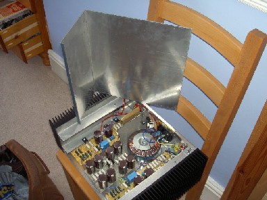
The chassis for this amplifier is one piece of 2mm aluminium sheet which has been bent to suit the dimensions of the heat sinks. This forms the bottom and the back of the chassis, to which all parts are connected. The chassis is connected to the heat sinks using 15mm equal angle 3mm thick and fixed using 3mm machine screws and nuts. The bottom has been liberally drilled with 6mm holes for ventilation. The angle fixing the top to the heat sinks has been tapped for m3 screws as it is the last panel to be attached. The top is 2mm aluminium sheet drilled with 6mm holes for ventilation and the front is a piece of 5mm aluminium.
The image shows the aluminium sheet used for the bottom and back. Actual image is for the F2 but the panel is exactly the same for F6.
The measurement

The plot approximates to 0.066% distortion. The signal generator used was a diy construct detailed here, which itself has a thd no better than 0.025% so a better result is unlikely with the equipment at hand. The signal was captured using an Acer I5 laptop using a Steinberg UR22 digital interface. The method used to arrive at this figure is documented here.
This configuration seems very susceptible to mains fluctuations. In the first version of this amplifier a random selection of irfp240s were used from the bit box, attached to the heat sink with 'sil-pads'. This version showed the bias moving quite considerably over a period of time, and was very difficult to get a stable idle point. It was first thought this may be caused by temperature fluctuations so a new set of matched irfp240s were substituted in, and the sil-pads were replaced with mica and goop. The new version displayed the same characteristics so more investigation resulted in these measurements.
It seems clear from the results that the mains variations during the test were quite considerable and had a profound effect on the bias point in this amplifier. With patience it was possible to set a bias point where both channels tracked together, and a point was set roughly in the middle of the high and low mains voltage positions.
More time is needed to determine if the mains fluctuations have an effect on sound quality.
The sound
Awesome!
It's been running while connected to various different loudspeaker types: full range, two way, reflex, TQWP, transmission line and OB. So far it's shone with all these types and to my ears it's as enjoyable as any of the amps documented here. I have found it slightly shy at the top end when trying to drive full range electrostatics, so this may be a combination to check first before committing.
Firstwatt B1
All the amplifiers detailed on this page are of the power amp persuasion. That is to say they have no level control and rely on some kind of pre-amp to provide volume adjustment. This is no problem at chez vitalstates as all the amps are driven by digital sources such as squeezebox and echo digital interfaces, all of which have in-built volume control. It does sometimes present a problem when taking the amplifiers to other peoples gatherings or audio meets, however, so this is one solution. As a pre-amp wasn't considered as a necessity it wasn't considered necessary to spend a lot of money, so this is again considered a major 'value for money' undertaking....
This is unashamed promotion for the B1 as it is fantastically easy to build and sounds fantastic as well (authors opinion).
The B1 is a passive pre-amp and therefore has no gain. It is however a buffer and provides good impedance matching between components. Many passive preamps seem to be criticised as dull and lifeless, but whether this dull and lifeless is caused by impedance matching issues can only be guessed at. You have my word for it, there is no dull and lifeless here. Full details and explanation, including circuits can be found on the Firstwatt site here.
Board layouts
In true DIY style the amp was built on matrix board. This is very easy as the circuit only consists of half a dozen components, but if in doubt ready made circuit boards can be bought from the Firstwatt site.


Again, in the interests of VFM, the B1 was housed in a modest plastic equipment box from Maplin. The box put the budget back by £7.50 but this is not considered to detract from the appearance. Indeed, the whole amplifier cost no more than £20 so its more than eligible to join the other offerings as representing good music for minimum outlay.
The B1 was recently run alongside a fairly expensive TVC based pre-amp at a DIY meeting and acquitted itself amazingly well. It was generally agreed the B1 held it's own against such exotic company, but it was only when the fact was leaked that the B1 had a £2.50 Maplin pot that the gravity of the comparison became apparent.
SV572 Single Ended
The SV572 amplifier is single ended with a 9 pin Aikido driver circuit. The output stage is configured slightly compromised so that the valve is swappable between SV572 and SV811. The differences between the 2 valves have been documented in some obscure corners of the interweb but curiosity dictated another look.
The amplifier started life on a breadboard with cathode bias and AC heating but has evolved considerably since the initial attempt.

The original amplifier

Harmonic distribution with ac heating
Rough calculation puts the thd somewhere around 0.3% for 1k signal at 1 watt, with marginally more 3rd harmonic than 2nd. At a slightly different operating point the manufacturer gives a figure of 0.2% for the SV811 so this result would seem reasonable.
The final amplifier

click on the image for a full description
2A3 SE srpp

The amplifier is a normally configured 2A3, i.e 320v anode, 48v bias, approx 60ma idling, driven by a bog standard srpp using 6SN7, with Hammond transformers and chassis. The output transformers are believed to be Tamura 2.5k, rescued from a suspiciously configured Chinese amplifier. The resulting sound is very detailed and dynamic but a little shy in the volume area. The circuit shown will produce only modest volume levels when driving speakers with less than 95db efficiency.

The amplifier was run-in for a few days with the ariel 6 speakers and the volume was always 'flat-out' in a 15x15' room. This was a bit of a surprise as the ariel was assumed to be a good match for a 2A3 until this point. Moving the amp to a larger room with vofo speakers was a revelation, however. In this situation, with the volume at 12 o'clock(half way) the level started to become uncomfortable. The difference between 92/93 db speakers and 95-96 db efficiency is profound to say the least.
It would be prudent to point out that the circuit as shown does not run the 2a3 to anywhere near its limit and a lot more could be squeezed out. However at this unstressed and conservative point the amp does sound very beguiling and gives more than a touch of the magic that is associated with the 2a3.
SRPP - other issues
Valve experts will hopefully forgive the naive and amateur discourse that follows:
I was musing about what-ifs and trying other srpp's for the 2A3 so I thought I'd have a go with 6sl7, mainly because the 6sn7 was a bit timid in driving the last design. At around the same time I noticed an article on the interweb regarding balanced srpp(the original link is no longer valid, although an article by Merlin Blencowe is a good read on the subject), and the fact that it might only be optimum when driving a load specific to the valve. Using the formula in the balanced article, I discovered that some published circuits were not using a load anywhere near that described by the formula, so I went in pursuit of the truth, using experiment instead of maths.
With the 6sl7 as a guinea pig I discovered that using a load (470k)common to a few published circuits the clipping was asymmetric, and at the same time the voltage gain was not consistent. This led to experiments with various loads on the same srpp set-up, the results of which are shown here. The upshot of this experiment showed that using a load pretty close to that prescribed by the balanced article formula, did result in a circuit which clipped symmetrically and also showed a consistent gain over the full range of input voltages.
The optimum load did cause the amplifier to sound much more crystalline and expansive to my ears. However, it is yet to be vetted by more discerning ears than mine.
At this stage I am not sure if this result will be similar or repeatable with other valves, but more experimentation is planned. I have discovered from other sources on the internet that asymmetric clipping is highly sought after in guitar amp distortion and is an ingredient in some guitar stomp boxes. That being the case, I definitely don't want it in my hifi amps...mmmmm.
2A3 with balanced 6sl7 srpp


Please use the Contact page to request further details.